Last time I showed you a pair of simulated-but-real-looking landing lights. Do you remember my discussion at the beginning of that installment about the ever-present need to weight the value of added detail against the value of the weight savings that doing without them offers? Those landing lights are a good example…I chose to include the detailed lights that you can’t help noticing, but to leave out the extra weight of a working light system that a lot of people won’t notice unless you point it out to them. Same game this time around. I’m going to devote a lot of time, effort and weight to several “gotta’ have” characteristic B-17 features but pretty much leave out the extra weight of the interior stuff that you MIGHT see.
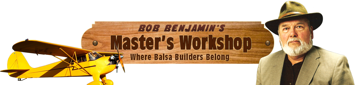
B-17-22-1 Let’s get started by playing “catch-up” fort a while. Do you remember the custom “half-turn” latches I created for the top cabin structure? It turns out that the 1/8” plywood plates I mounted them to were not blended/sanded to match the surrounding balsa structure as well as they should have been. Here’s the outside of the rear latch assembly…if you look carefully you’ll find a few places where the edges of the plywood are going to show if I don’t do something about it.
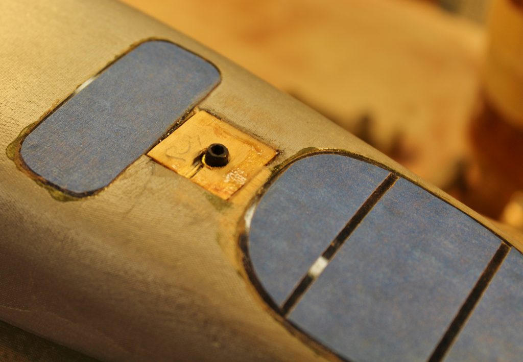
B-17-22-2 Looking at the front latch now you can see how I used a generous “plastering” of good old cellulose auto body putty. You’ve seen me work with this stuff before, so you already know how it will look after I finish sand it.
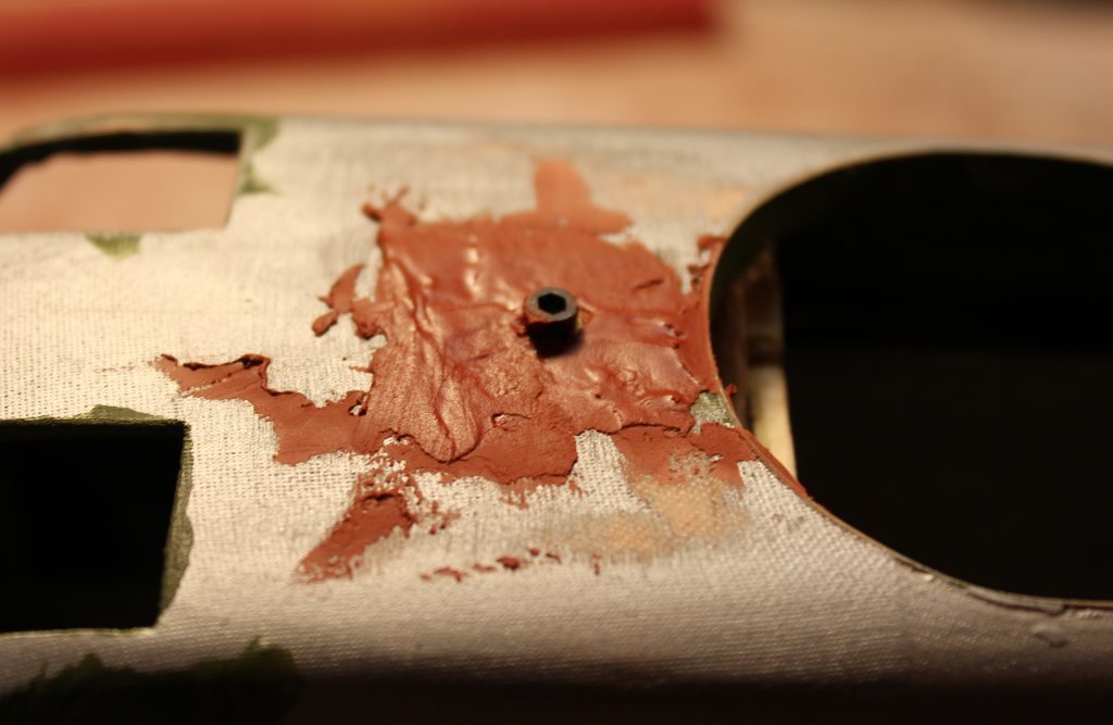
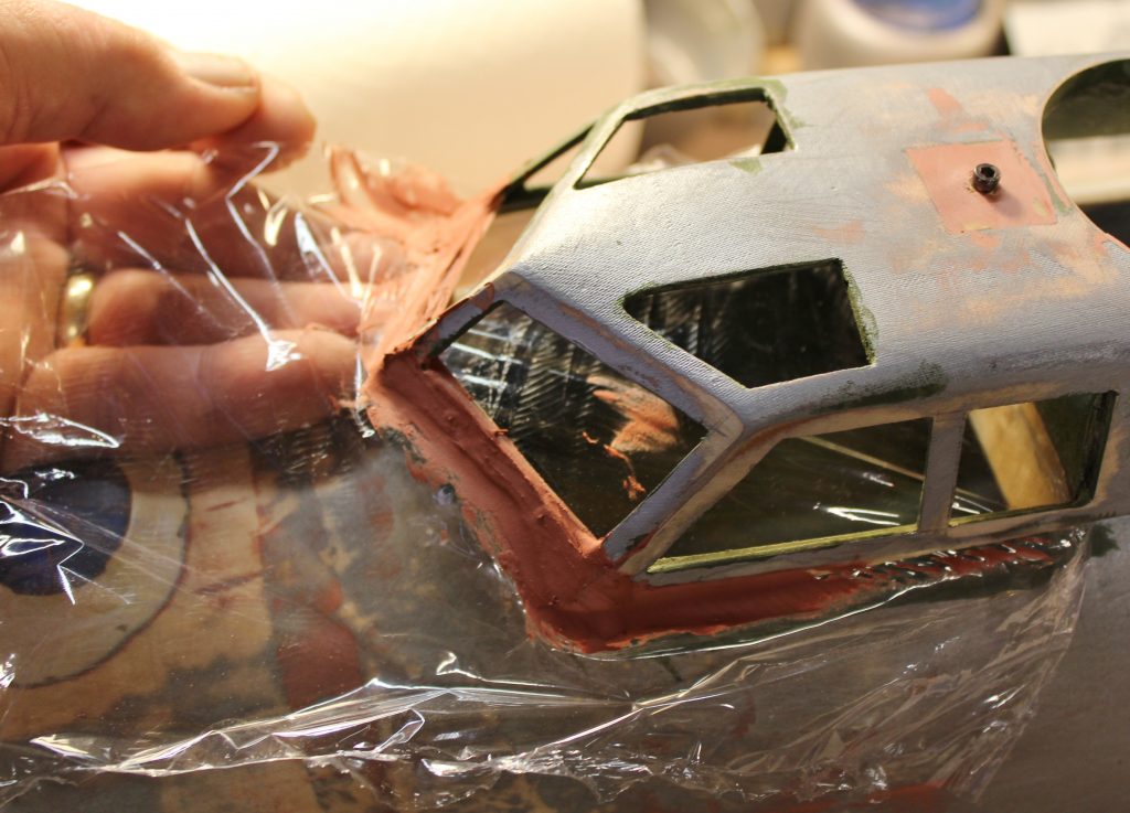
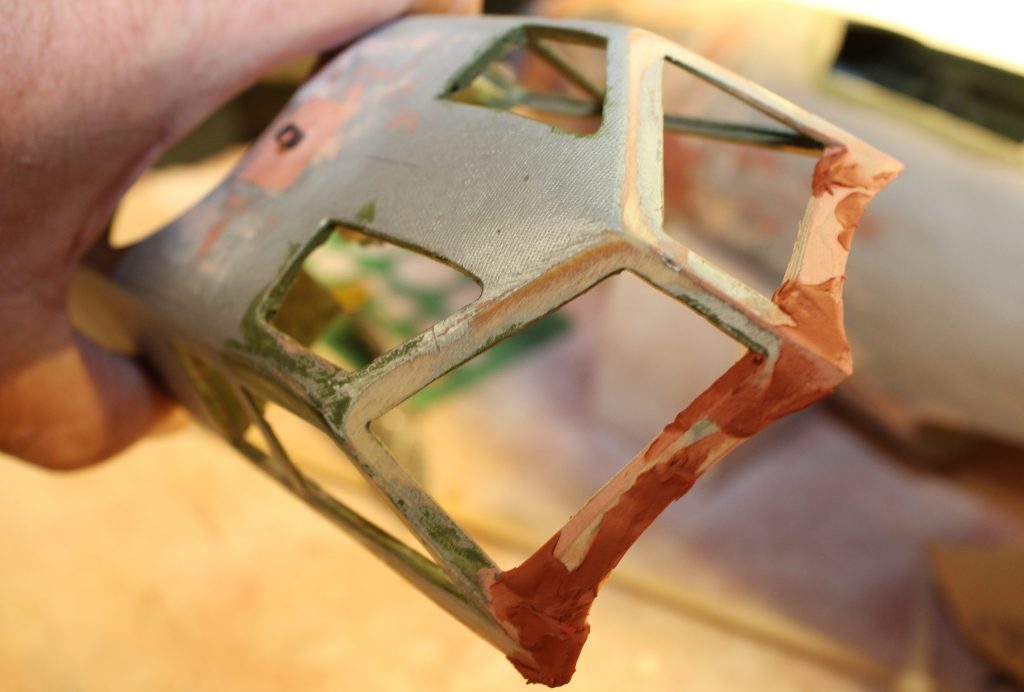
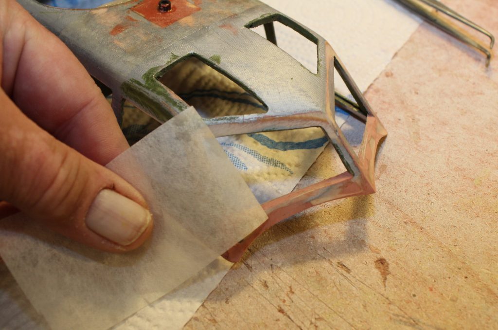
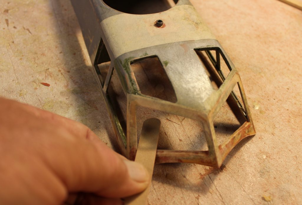
B-17-22-3 This is the front/cockpit/windshield portion of the removable cabin structure. As I have mentioned before, this is one of those “eye magnet” places that will draw the attention of everyone who looks at your model. If you permit yourself to do sloppy work here, they will see it. The biggest single problem is that the cabin top detaches from the main fuselage at the base of the windshield and side windows. Doing it like this is just about the only practical way to get real-world access to your flight batteries at the field, but the structural break there in the full-scale B-17 is no more than a series of sheet metal panel lines. My solution to the problem was to accept the separation joint and camouflage it with the best-fitting joints I could make. I had already done that several sessions ago, but working on the surface/finish base since then made enough changes in the fit to demand that I take the time to go back and fix them. I did that by adding a generous fillet of more of that red auto body putty stuff. This is light/soft enough that I’ll be able to do some really delicate shaping/sanding with it, but it will need some extra help to become real world durable. I started by taping a big sheet of clear wrapping film across the entire fuselage surface that’s involved, latching the cabin assembly tightly in place, forcing red stuff into every possible crevice and then building up an exaggerated fillet as well.
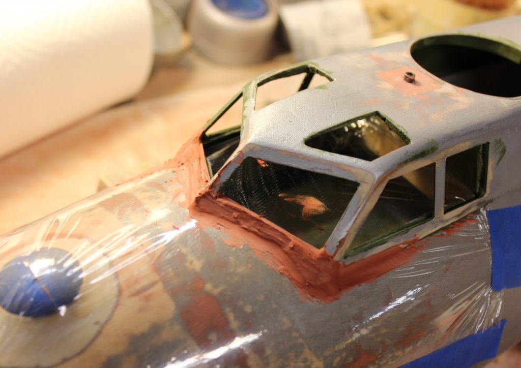
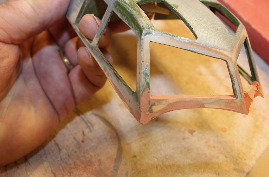
B-17-22-4 When I was sure that red stuff had dried all the way through I backed off the cabin top latches and “popped” the entire cabin top loose. You can see how the fillet material comes away from the clear wrap and stays attached to cabin structure.
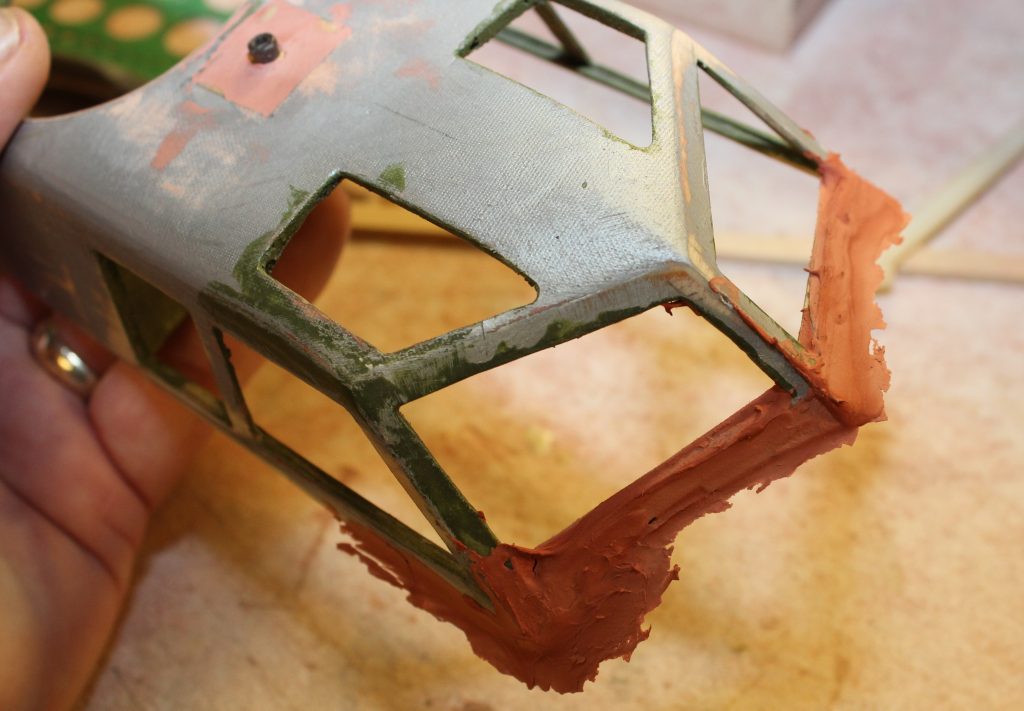
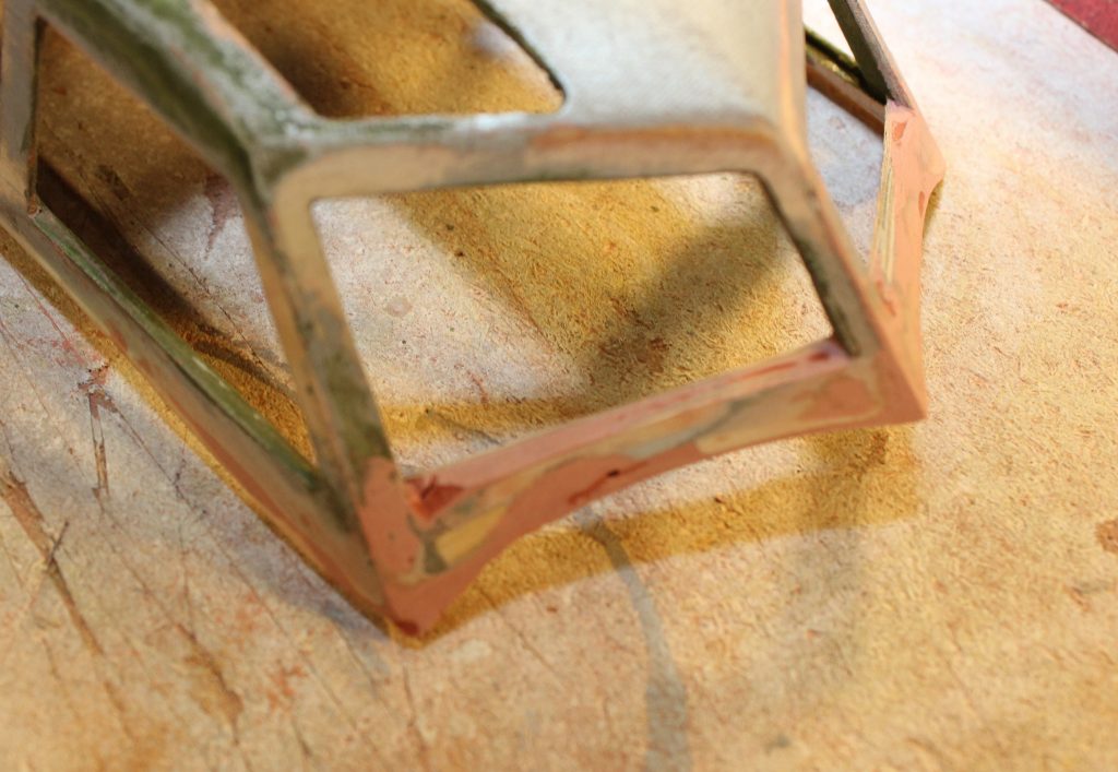
B-17-22-5 When I lift the assembly free of the rest of the airplane it looks like this.
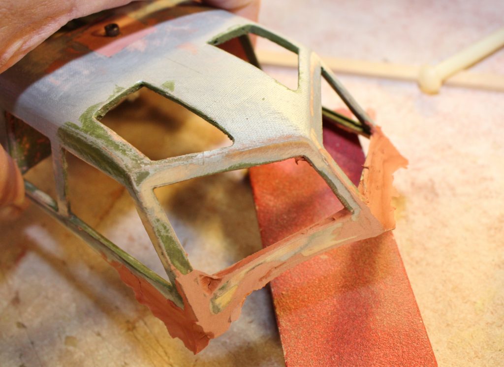
B-17-22-6 This where that “delicate touch” stuff comes in. You need to be absolutely certain what shape/profile you want to create before any sandpaper touches the work.
B-17-22-7 I have made a start at cleaning up the right windshield panel frame. A No. 11 blade was the best way to get into that tight corner…
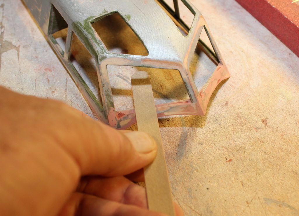
B-17-22-8 and another emery board fits neatly inside the cutout without threatening to gouge up the parts I don’t want to change.
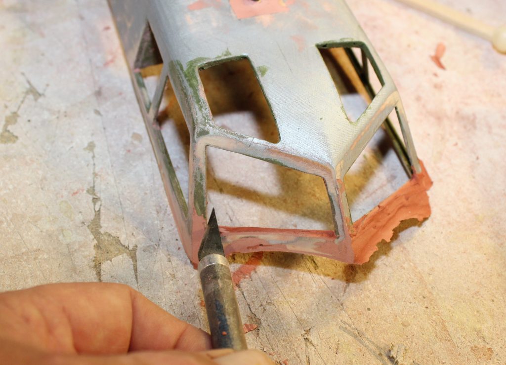
B-17-22-9 And after all that I still found a few low spots that were betrayed by the deeper red color where the sandpaper didn’t reach. Trust me…you need to fix these.
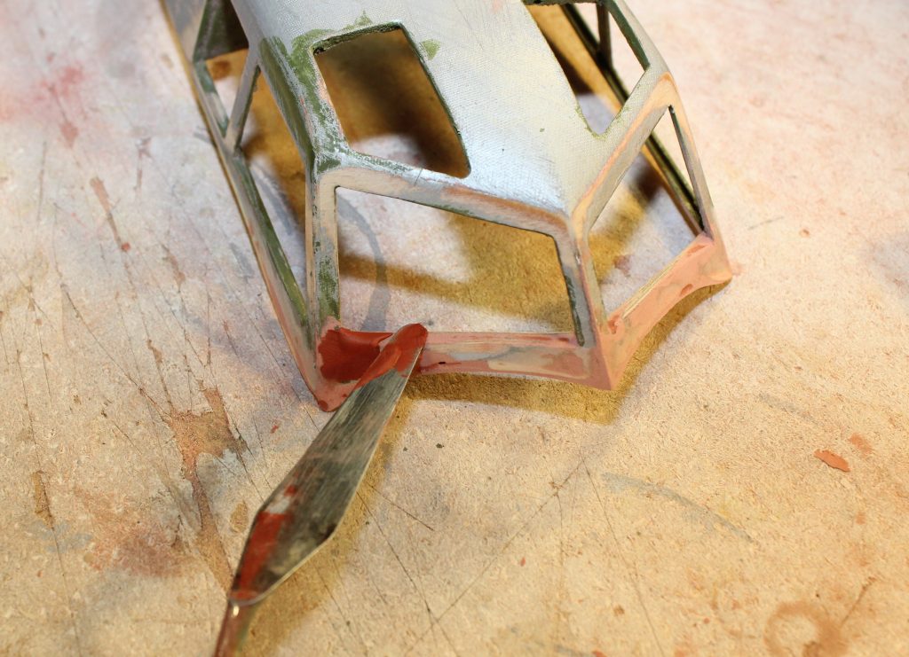
B-17-22-10 I did that by plastering on just a bit more red putty.
B-17-22-11 Wherever I suspected the chance of a low spot or a crack I hadn’t noticed I added more filler until the “second coat” looked like this.
B-17-22-12 Sanded again, the right windshield looked like this. You can still see a few dark spots on the left side that I’m not finished with yet.
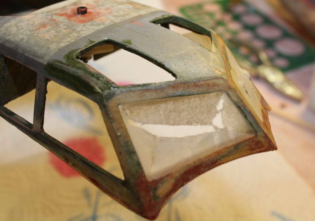
B-17-22-13 Remember the “delicate” part of all this that I mentioned? Without some help that thin exposed lower edge won’t last long “in service”. The answer is a few more scraps of silkspan applied wet into a wet base of EzeKote.
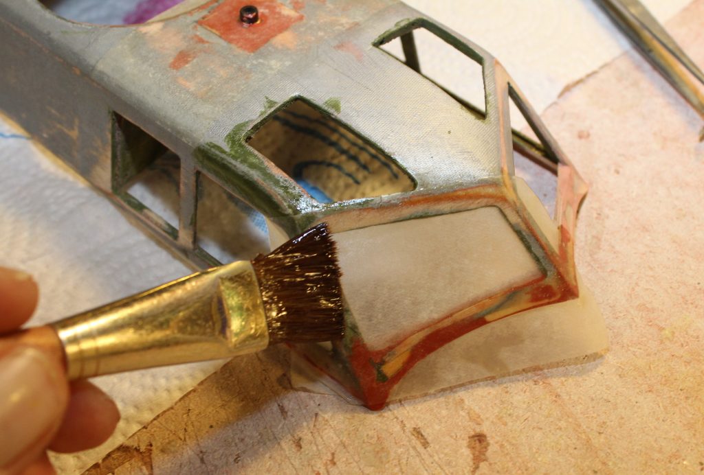
B-17-22-14 With the silkspan “patch” in place I gave the entire windshield a generous application of more EzeKote…
B-17-22-15 and let it dry properly. When that happened it looked like this.
B-17-22-16 Then I went back to trim the excess silkspan out of the open portion of the windshield frame and finish sand all the edges with another emery board.
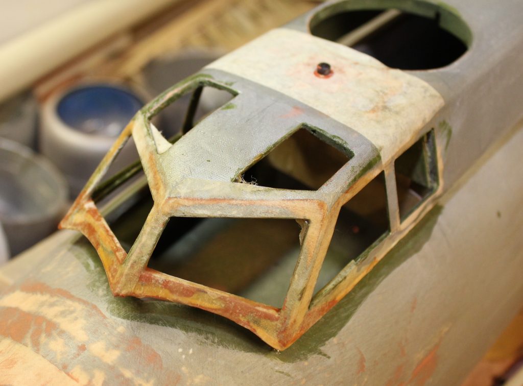
B-17-22-17 All done, that looks like this. Can you see the additional silkspan I added across the cabin roof ahead of the top turret opening? NOTE: The cabin top is still fitted loosely here, latches open, so you can see the panel edges I made. Later you’ll get to see it secured for flight.
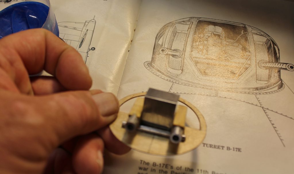
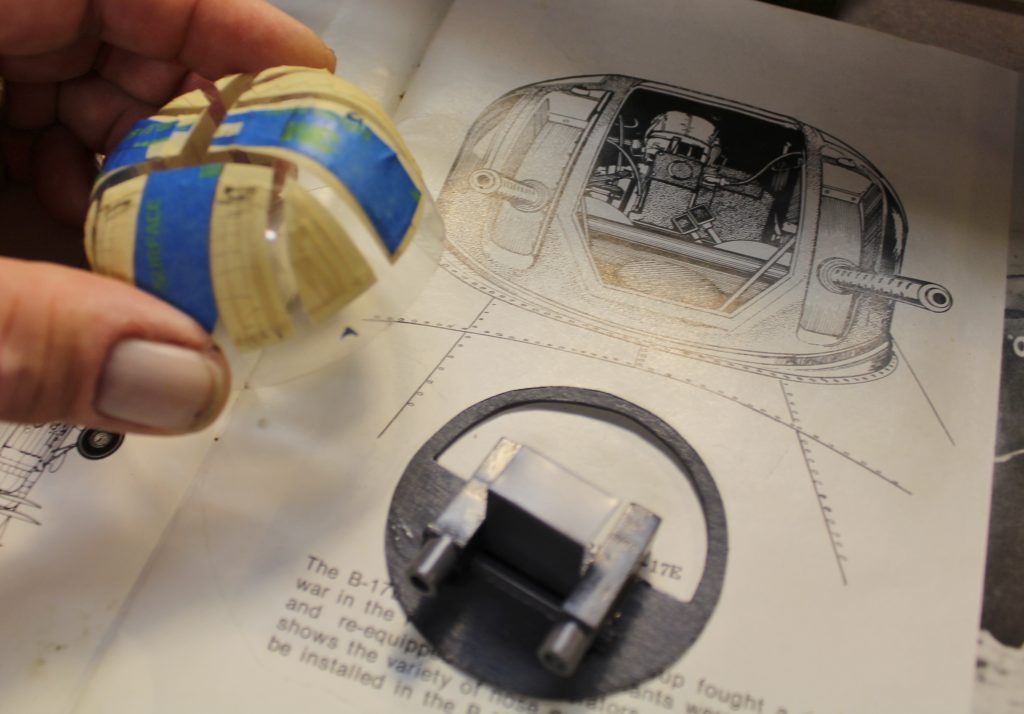
B-17-22-18 Yeah,, there’s a “top turret hole” there, so I’m going to need a top turret to fit into it. Here’s how that began. The top turret on a B-17 is another of those places where there’s enough detail to tempt us far beyond anything reasonable for a model of this size. What about a full-bodied gunner seated in a rotating turret with a fully detailed pair of 50-cal M-2 machine guns? Sorry, that’s not going to happen here. We’ll leave that stuff for whichever of you ends up building the twenty-foot span B-17 that could carry that much extra weight. However, we need something in there. Let’s start by realizing that the top turret gunner doesn’t always ride there…we’re not in combat right now and a very simplified mount and gun barrels will look just fine from a few yards away. With that in mind I went back to study the scale references again and figured out which details I would need to include to pull off that illusion. Here’s what I came up with. The base plate is 1/32” plywood cut to approximate the shape of the gun mount that’s open at the front end for the gunner to poke his head and shoulders through, along with some scraps of plastic tube, basswood and lithoplate for the rest.
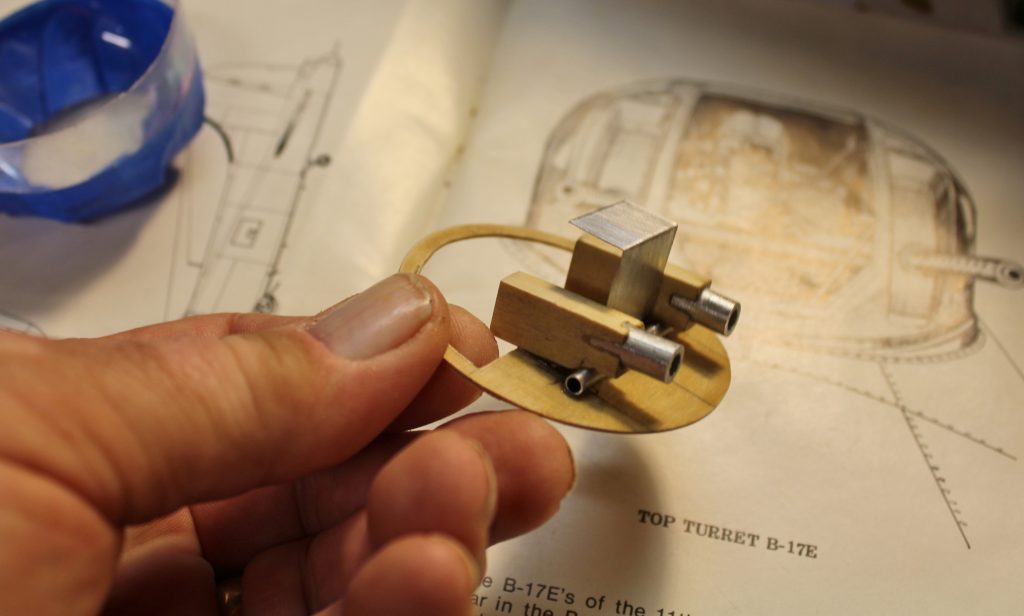
B-17-22-19 The whole thing looks like this from another angle. The dummy gun barrels will come later, along with some dark gray paint. You can see the partly masked-off turret molding upside down in the background.
B-17-22-20 Here I’ve finished the interior paint job and completed masking off all the details of the turret. The exterior paint job will go everywhere the clear base is exposed to simulate the metal turret framework.
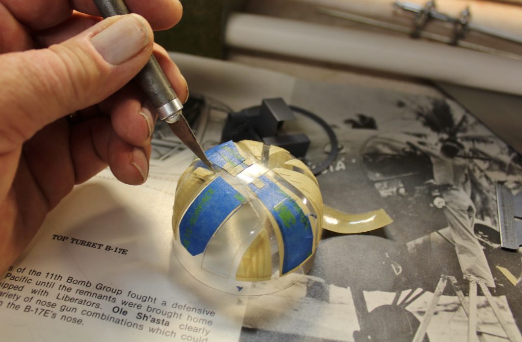
B-17-22-21 A really sharp (new) No. 1 blade was the tool I chose to cut/trim out the slots through which the 50-cal barrels will protrude and elevate.
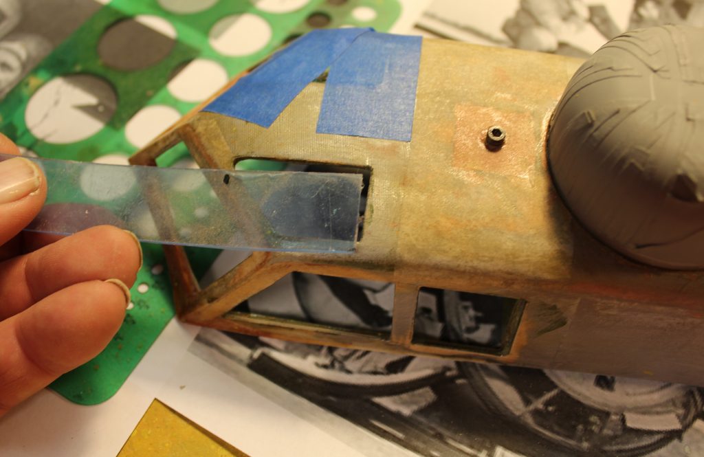
B-17-22-22 Right now I’ll work on the cockpit windows. I’m using more of that heavy clear plastic that worked well for the rest of the windows. Here I’m checking the width of a strip from which I’ll cut the left (pilot’s) overhead panel. The co-pilot’s is already in place and secured by that blue masking tape.
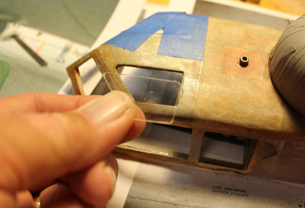
B-17-22-23 Cut to fit and ready to press into place, the pilot’s overhead window looks like this…
B-17-22-24 and I’ll start taping it into position like this. NOTE: I determined beforehand that the tape has enough “grab” to pull that front corner fully into place and hold it there.

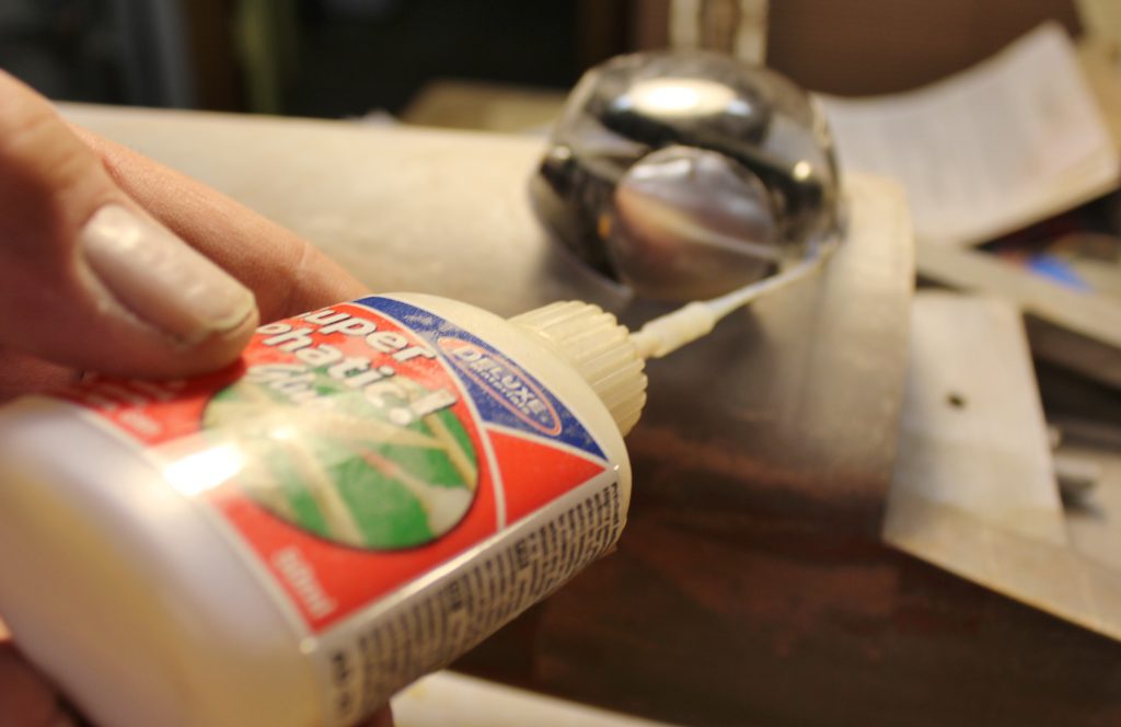
B-17-22-25 Just as I did with the top turret, I’m using a very-carefully-applied bead of Deluxe Materials Super Phatic from the inside to fix the overhead panels in place.
B-17-22-26 The results of that effort look like this. The Super Phatic on the right has dried and turned clear; on the left it is still wet and milky-looking.
B-17-22-27 That’s right…there’s always more sanding to do. Here I’m making yet another pass over the fuselage nose with some 320-grit production paper. (Yes, I DID find a few more “ugly seeds” that needed to be removed.
B-17-22-28 And at the other end, I decided that the hollowed-out inner circumference of the tail gun housing/fairing needed a better finish and added this liner of 1/64” plywood.
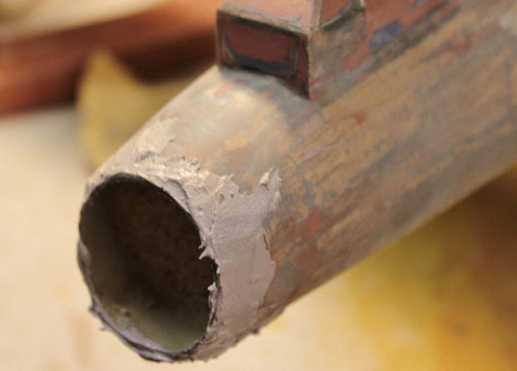
B-17-22-29 To provide “something to sand on” at the trailing edge of the opening, I added some catalyzed polyester autobody surfacer. This stuff cures HARD and the exposed finished edge will stand up without cracking.
B-17-22-30 This is the belly turret going into place with more Super Phatic. There’s no masking yet …I’m going to do that with the turret in place to make it easier to hold on to.
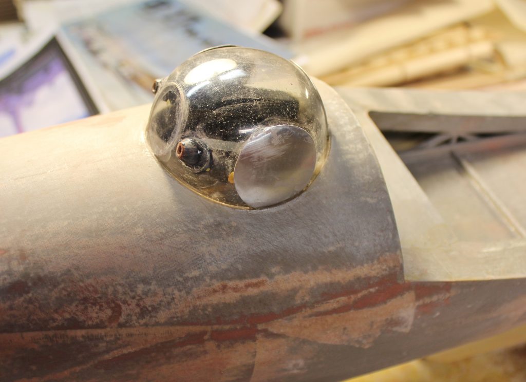
B-17-22-31 All mounted it looks like this. As with the top turret you’ll have to wait to see how the gun barrels are going to look.